 button) will create a RISAConnection file (with a .rcn extension) and a RISA-Tekla Link exchange file (with a .exc extension) and will be located in the same directory.
 When transferring Tekla Structures connections to RISAConnection the majority of the behavior is similar to standalone RISAConnection. For this behavior view the RISAConnection General Reference which can be found on the Documentation page of our website at risa.com/d_documentation.html
This topic details specific variations from the standard RISAConnection behavior. To learn the steps of taking the Tekla Structures model to RISAConnection, view the Tekla Connection Procedure topic.
When first coming into RISAConnection from Tekla Structures you will see that the file is populated with all of the VALID connections. Thus, only connections that RISAConnection can actually design will be brought over. The act of invoking RISAConnection from Tekla Structures (using the button) will create a RISAConnection file (with a .rcn extension) and a RISA-Tekla Link exchange file (with a .exc extension) and will be located in the same directory.
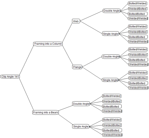
Once you have imported your information in RISAConnection, you will see that the connections are grouped in the Project Explorer.

The groups in RISAConnection are based on the connection component numbers from within Tekla Structures. Within each Tekla Structures component connection, however, there are also groupings based on whether the members are framing into a column or beam, whether a column/beam connection frames into the web or flange of the column, what the shape type is, and so on. Therefore, a single connection component from Tekla Structures could create a large number of connection groups in RISAConnection.
In the Project Explorer there are three levels: Project level, Group level, and Connection level. These levels are nested within each other and allow you to change design and connection properties quickly and easily. There are also properties that can only be changed within Tekla Structures. Here we will discuss these different connection property categories and how to use them properly.
Items that can only be modified from Tekla Structures:
If you wish to modify any of these properties you need to go back to the Tekla Structures model, make the change, and then re-export to RISAConnection.
When you click the project label in the Project Explorer, the Project Properties are then shown.

Here you can update information in the Project Description fields and some of the options from the Global Parameters - Solution tab.
Note:
When you click on a Group in the Project Explorer then the Group Properties are shown.
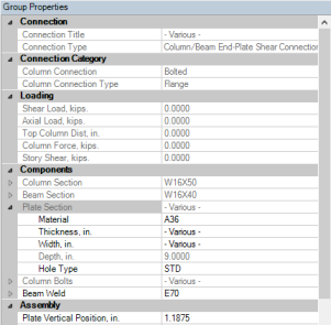
In the Group Properties you can modify connection properties for all of the connections within this group at one time. The grayed out properties are properties brought over directly from Tekla Structures; these properties can not be edited in RISAConnection.
Note:
When you click on an individual connection, that connection's properties are shown.
The grayed out properties within an individual connection may be either Tekla Structures controlled or Project level controlled. You must go up to those levels to change these properties.
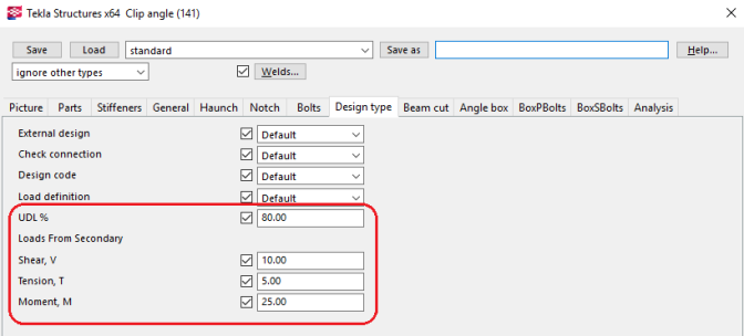
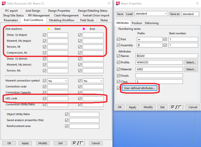
RISAConnection accepts the Shear, Tension, and Moment fields for each connection. It will also accept a value in the UDL % field in place of the Shear, V. Please see the UDL section for more information on how this works.
Double-clicking on a member and clicking the User-defined attributes... button and going to the End Conditions allows a user to define end reactions on a member. These end reactions will then be transferred to RISAConnection appropriately. Note that you can use the UDL code field in place of the Shear, Vy (major). Please see the UDL section for more information on how this works.
Note:
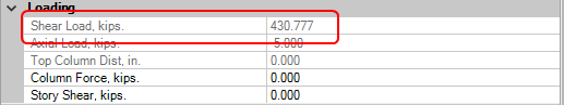
The UDL % is a way to have the link calculate the design shear forces on a beam in your model. This is done considering the AISC 14th edition manual Tables 3-6, 3-7, 3-8 and 3-9 for wide flanges and channels. These tables have a Wc/Ωb for ASD and a φWc for LRFD and units of kip-ft. Using the length, L, and the UDL % input the shear force calculation is as follows:
VASD = (UDL %) * ( Wc/Ωb) / 2L
VLRFD = (UDL %) * (φWc) / 2L
This value is what will be brought into RISAConnection in the Shear Load field in RISAConnection.
Note:
RISAConnection allows you to use Custom loads that are not pulled from Tekla Structures. If you choose this option then the Tekla Structures forces will come in but the custom forces will be used.

Once you get the connections configured properly you need to solve the model. You can solve the model by connection, by group or for the entire project by pressing the appropriate button 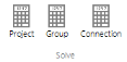 to solve either a single Connection, Group or the entire Project.
Note:
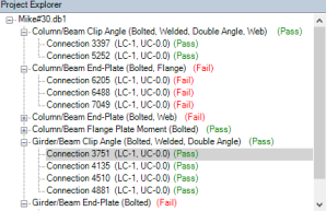
Once you have a connection, a group, or the entire project solved you will be able to view results via the Project Explorer or Reports tab.
The Project Explorer gives a summary of the design results for the project. Each connection gives a Pass or Fail notification, along with the Max UC and the LC that produced it.
The Group will state "Pass" if all of the connections within the group passes. It will state "Fail" otherwise.
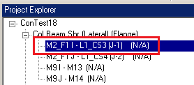
If a property is changed then the connections whose properties are affected will be invalidated. If you modify a single connection then the results for that connection will be invalidated and an (N/A) will be shown.

In this scenario you can simply re-solve that connection to get results again.
If you invalidate a group property then that will invalidate all of the connections within that group. If you invalidate a project property, then it will invalidate all connections in the project.
The Report view gives the unity checks for each Limit State. value. The Reports section will show which Limit State produced this value.

If the connection you are viewing has its results invalidated by changing a connection property, then this message will be shown:

If this message is shown then the results shown are invalid. Pressing this message has the effect of solving that individual connection. The program will then give valid results for this connection.
Once you have your connections configured properly you can take those results back to Tekla Structures to be viewed in the RISA-Tekla Link browser and graphically by pressing the  button in RISAConnection.
This will do two things:
1. Open the RISA-Tekla Link results viewing dialog and show graphically whether a connection passes or fails.

For more information on this dialog see the Application Interface topic.
A green cone indicates a passing connection:
A red cone indicates a failing connection:
2. Update the model for updates made in RISAConnection. This will physically change your Tekla Structures model to match the RISAConnection properties.
The Tekla Structures and RISAConnection integration is meant to be used for multiple round-trips. You can go back and forth as many times as necessary to complete your project. See the Workflow Diagrams section for more information on this.
Note also that there is the  button that will automatically roundtrip the model from Tekla Structures through RISAConnection and back to Tekla Structures. This is NOT recommended for the first time solution in RISAConnection, as it will make many automatic changes with no real warning. However, if you have manually transferred to RISAConnection a few times and want a quick solution again then this button can be valuable.